
Diffuse Optical Wireless Communication
In general, there are 6 types of configurations in IR wireless systems and can be classified into 3 groups: (i) Directed vs Non-Directed links, (ii) Line-of-Sight (LOS) vs Non-Line-of-Sight (Non-LOS), and (iii) Hybrid links. Figure below shows the classification of the various infrared links.

Classification of infrared links [1]
In directed links, the transmitters emit light within a narrow angle and the receivers can collect light within a narrow field of view. Thus, directional transmitters and receivers must be aimed in order to establish a link. Non-directed links on the other hand, employ wide-angle transmitters and receivers, thus alleviating the need for such pointing.
Directed link design maximizes power efficiency, since the path loss and reception of ambient light noise is minimized. Non-directed links, though more convenient to use, particularly for mobile terminal since the aiming of the transmitter or receiver is not required, has much lower power efficiency.
Another classification criterion of the link design relates to whether the link relies upon the existence of an uninterrupted line-of-sight (LOS) path between the transmitter and receiver. Non-LOS link design generally relies upon reflection of the light from the ceiling or other diffusely reflecting surface.
Non-LOS link design increases link robustness and ease of use, allowing the link to be used in the presence of barriers such as people or cubicle partitions that stand between the transmitter and receiver. LOS link, on the other hand, has the advantages over its counterpart in power efficiency and less multipath distortion.
There exists another classification of links, the hybrid links. Hybrid links combine transmitters and receivers having different degrees of directionality.
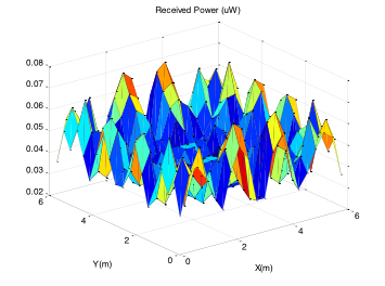
To enhance diffuse link, computer generated hologram (CGH) is used to generate multiple beams when irradiated by a modulated IR laser beam. The multiple beams when strike on the ceiling of a room would form a modulated spot pattern and light is further scattered in different directions resulting in a relatively uniform light environment. The latter is at the expense of multiple dispersion signal problem as uniformity requires different light paths arrive at the same point in space. The company developed a spot pattern optimization technique that gives a good performance balance in the uniformity of received power distribution and multiple dispersion effect.
Interested party looking for spot pattern that yields a balanced light uniformity and multiple dispersion effect is welcomed to send in your requirement. We can also provide the CGH design that generates the optimized spot pattern upon irradiation.

Optimized spot patterns and signal power distribution for FOV of (a) 90°,
(b) 45°, (c) 30°, (d) 20° and (e) 10°.


[1] John R. Barry, “Wireless Infrared Communications”, Kluwer Academic Publishers Group, USA, 1994.